My start in building robots
Preamble - Stepping back to learn and play
I left Thunk AI at the end of November of last year. I spent just over a bit over a year there as an engineer working on the the AI agent platform. I’m proud of the work. But, I decided to step back from Thunk for the moment. I’m now starting a new learning cycle like the six or so months before I joined Thunk. It’s amazing how much you can grow if you can find the time to look around and really learn new things. This is difficult when you’re heads down working on making a product like I have for most of my career. I feel blessed that I can do this. I don’t know how true innovators find the mental bandwidth to bring new things into their existing work and still do the day-to-day stuff. That is truly a skill.
So now I have the time again to learn new things. Lately, I’ve been getting into robotics. I want to share my early experience thus far from the perspective of someone coming from over 30 years of doing nothing but software.
This post is first in a series documenting this journey. In this first part, I share with you my initial robot arm build that I started before I joined Thunk back in 2024.
I wanted to just build and learn something
I started building the Arctos Robotics arm in the summer of 2024. Initially, I didn’t define a concrete goal. Earlier in the year, I had to be diving deeply into LLM, Reinforcement Learning and Agents. I had a feeling that learning to apply RL to robotics would be challenging and fun.

TBH, I didn’t do a great deal of research before deciding to build the Arctos Robot. I was initially really impressed with how it looked and thought it would be cool to learn about the mechanics of a robot rather than purchase an assembled arm. The only mental checklist that I had before deciding to build it was:
- Was there evidence of an active community and people successuflly building it?
- Was the software open source?
- Did it look like it would be rather inexpensive to build?
I found the discord server and it seemed that people were active. The website also linked to a series of videos (live streams) by Unexpected Maker. That crossed off #1.
The website linked to a github repo. Check off #2. Estimates were just over a 1 kg of filament for the core arm, about $400 for the motor and hardware kit and another $45 for the CAD files. Check off #3.
I’ll share a new checklist later in the series that I would use now, with the help of hingsight, later in the series.
Take my money
I paid the ~$45 to get the CAD and STL files (which was a janky experience), ordered the kit from AliExpress and started printing on my new Prusa MK4. I should note, at this point, I had 30 years of experience working in software, machine learning, and marketing. Here is where I stood on other skills:
- 3D Printing - up this point was mostly watching my son print fidget toys and Dummy 13s on a friend’s Prusa mini.
- Electronics - I had never soldered before. My exposure to electronics was limited to a few experiments from the Make: Electronics book and putting together a waveshare RC car over Thanksgiving break in like 2017.
- I didn’t know how touse any CAD software like Fusion 360.
I did not know what I was getting myself into. And, that’s kinda what it takes to be a tinker I guess.
While I waited for the motor kit, I watched a bit more of the Unexpceted Maker’s videos trying to pick up tips as he was building. But, I didn’t watch all of them, because they were each 6 hours long. I should have. I virtually flipped through the only real documentation which was the assembly guide. I lurked on the discord channel, which was difficult to navigate.
Once the kit arrived, I was able to put the the X-axis together without much fuss.
How do you RTFM when there is no M?
I proceeded to put the Y axis together and then it became clear, I needed to start over and wire the motors as I proceeded because it appeared that there was no room for working with the wires after assembly. But, the assembly manual didn’t hint at wiring at all and the slim documentation and videos by Arctos himself on the website only discussed how to configure the stepper motors and there was nothing about how the wiring should actually flow through the arm.
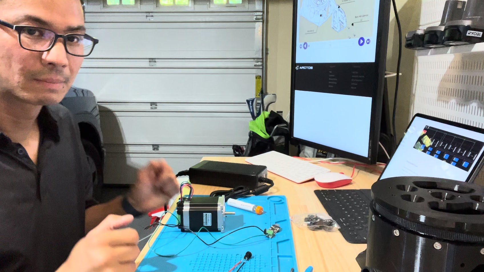
To make things worse, there are two ways to wire the robot and control the motors, an “open loop” and a “closed loop” method. I had purchased the closed loop because that’s what Unexpected Maker did and the website suggested it was where development was going to be focused. The motors had a controller attached to them that communicated with another controller board of a CAN bus. The example scripts for running the motors took G-Code as input and converted to the CAN messages. I had never heard of G-Code and vaguely remembered that CAN bus had something to do with a recent rise in car thefts.
It was a this point that it was clear to me that the documentation was incomplete and often out of date. There was no clear issues list to be found and the only real support was from the kindness of others on the discord server. I had to browse through the history of multiple channels and review Unexpected Maker’s videos to pick up tips on assembly and wiring tips.
Even Unexpected Maker struggled with putting the arm together and in one video admitted that he had to tear his arm apart because he also didn’t run the wiring as he was assembling.
After watching this video, I figured out how to configure and wire the closed loop controllers for the stepper motors outside of the arm. I was able to get the example script to home the motors, but I couldn’t understand how the G-Code was supposed to be converted to specific CAN messages. It just seemed like voodoo. That is until I found messages on discord where people shared links to Makerbase’s documentation on the CAN message formats. And, then it occured to me that the G-Code was a generic language for controlling robots, 3D Printers and CNC machines and these needed to be converted to specific instructions for the device. In this case CAN message that stepper controller boards understood.
I realized that I needed to plan the build out more in advanced. I spent time studying the design in Fusion 360, planned out how I was going to wire the whole damn thing. I also realized that I was likely to make a lot of mistakes along the way, so I need to make sure that my wiring strategy would allow me to tear things apart if I needed. I ended ordering a bunch of these T Tap wire connectors. I would eventually end up also using WAGO connectors.
Pushing through
I slowly printed the parts (some taking 20+ hours) and put together the arm up to the A-axis over a few weks. I was feeling proud of myself because I thought in spite of the low quality documentation, I was able to put it together. That was two cyclodial gears for the Y and Z axis. I had never worked on anything mechanical before and it was fun to learn. But, then I started working on the plantetary gears for the A/B/C axis. The assembly was really painful. I don’t know what the decisions went into the design, but I believe this to be not designed to be assembled easily. The hardest part was keeping the parts of the gears in place while screwing them together within the semi-assembled gear system. I was inspired by some of the “tool” parts that came with the Prusa MK4 and MMU3 kits that were meant only to assist in the assembly. So, I ended designing and 3D printing tool that merely held the gear parts in place.
When I did some initial assembly tests of the B and C axis, it became clear that something was wrong. The arm made sudden jumps when the Y or Z axis were moving with the A, B and C axis attached. With the extra weight, it became clear that I had a lot of backlash in the Y and Z axis. I noticed some play while assembling, but didn’t think anything of it. Again, I had not mechanical engineering experience and didn’t even know what backlash was, let alone have the initution that the backlash I was seeing while assembling was no bueno.
How does it work?
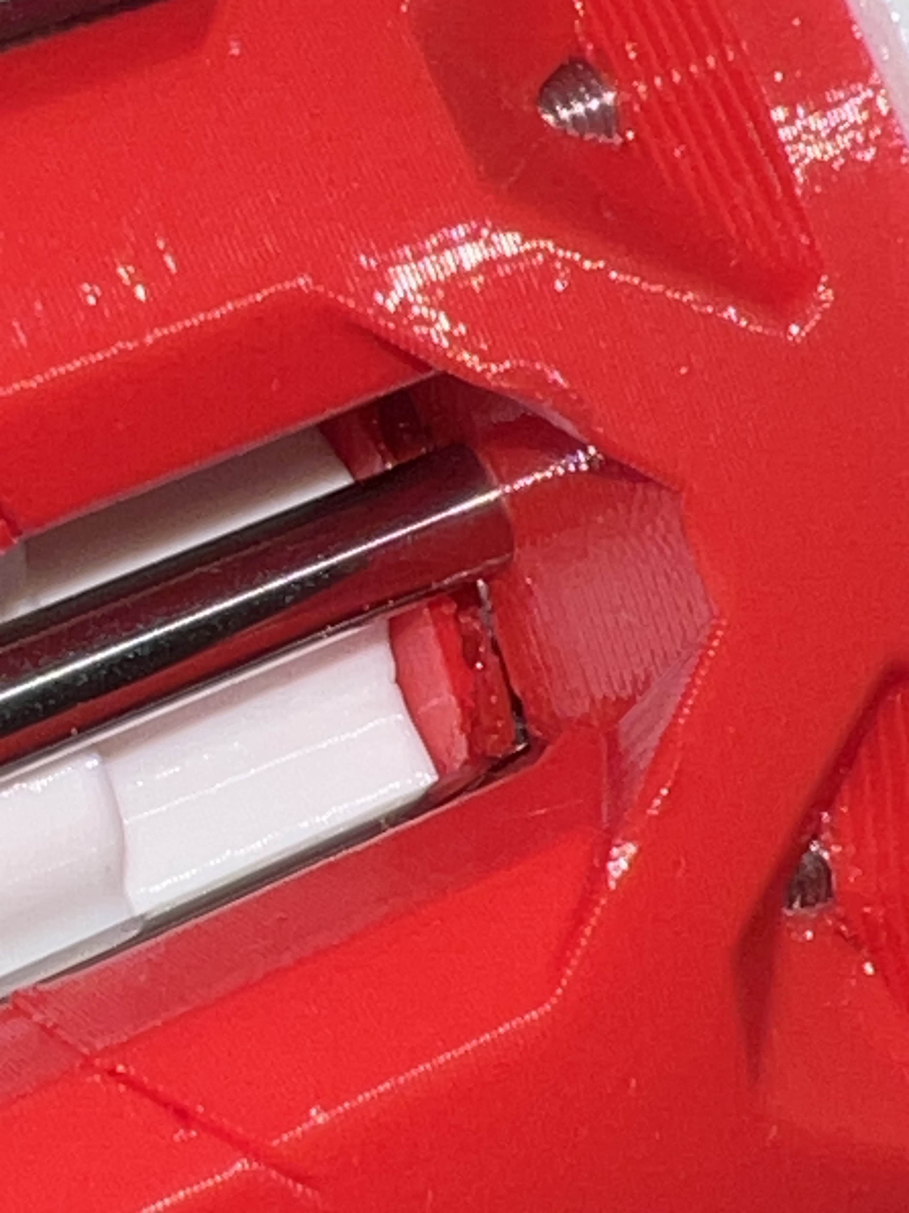
I proceeded to debug the problem. Tearing things almost all the way back down and putting it back together a couple of times. I tried to isolate why I was getting so much play in the Y and Z axis. I tried to describe my problem on discord. No help. But, looking around the Z axis gears, I noticed some of the plastic housing for the gearbox had broken. It’s likely that I tightened something too much. I needed to rip apart the Z gear box and rebuild it all over again!
I parallel, I was trying to understand how the B and C axis worked. There are two motors, but they do not independently control a single axis like the rest of the motors. I was confused as hell how this was going to work. I searched the discord and it turned out that Unexpected Maker had the very same questions. He asked around and the conversation that proceeded snowballed into a real mess. I think this interaction eventually caused Unexpected Maker to leave the channel and abandon the project.
Puff and just like that, he’s gone
I was almost two months in and I was starting to get frustrated with the slow build, confusing assembly instructions, unexpected backlash of the gears. I decided, I just need to get something end to end working. It didn’t need to be perfect. So, I told myself to move forward and get something working end to end.
But, then as I was reassembling the A-axis, I accidently swicth the polarity of the power cables and I smelled “magic smoke” come out of one of the controller boards. The makerbase boards don’t have any protection for this foot gun. And, it appeared that I had successfully destroyed two motor controller boards and even the CAN bus controller. The irony is that I had just read about someone else doing the same thing the day before. Welcome to the club I guess?

I had to reorder the parts and it just so happened to be backed ordered. And, I was just about to start a new job at Thunk.ai. So, I put the arm on hold and it sat in my garage workbench for over a year just collecting dust.
Next
In the next post, I pick up where I left off with the Arctos Robot after stepping back from Thunk.